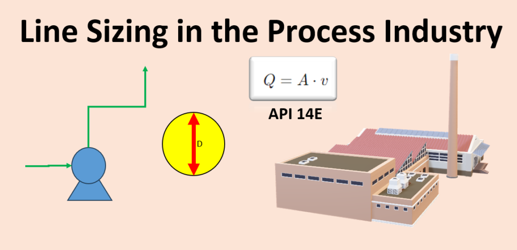
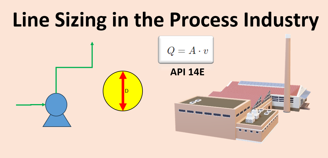
Hi, let’s start the discussion on “Line Sizing in the Process Industry.” Thanks for the previous response to my last article on line sizing calculations. Today, we are going to cover the line sizing procedure with a bit more clarity.

In today’s section, we will cover compressible and non-compressible fluid line sizing, single-phase and multiphase line sizing, key parameters involved in pipeline sizing, and the essential formulas needed for accurate line sizing. Let’s dive into the article.
Table of Contents
What is line sizing? Line Sizing in the Process Industry
It is a procedure used to size the pipe according to the required flow and process conditions. It helps to achieve the optimum line size, considering allowable pressure drop while avoiding erosion in the pipe and addressing cost considerations. Incorrect line sizing may result in higher costs or erosion in the pipe. Additionally, from a safety point of view, improper sizing is not advisable.
Compressible fluid line sizing
What is meant by compressible fluid?
A compressible fluid is one that can be compressed, meaning its density changes with respect to variations in pressure, temperature, or the composition of the fluid.
Designing the pipe diameter for compressible fluids is important but challenging. You must use the ideal gas law to determine the density according to the process temperature and pressure.
In the process industry, gases and vapors are considered compressible fluids. Gases like air and nitrogen are commonly used in various industries. Vapors must be considered in processes such as distillation or vaporization.
Non-Compressible fluid line sizing
Non-compressible fluids are those whose density remains constant and will never change. An example is water. Line sizing in this case is easier compared to compressible fluids
Single phase line sizing
Single phase line sizing in the process industry refers to the line sizing for a single phase, such as line sizing for liquid phase or line sizing for gas phase. This can further be divided into line sizing for compressible fluids and non-compressible fluids
Multiphase line sizing
Multiphase means that the fluid may have multiple phases, such as a fluid containing vapor as well as liquid. A pre-condenser or post-condenser line is a common example of this. Steam is also one example.
Key Consideration for line sizing in process industry
Following are the key parameters that you should consider before starting the line sizing calculations.
Flow Rate
Flow rate is the main parameter that we must know for the calculation of line sizing in the process industry. In the continuity equation, we use this flow rate to calculate the required diameter.
To determine the flow rate, you should go through material balance or energy balance; from there, you will get an idea about your flow rate. In this step, also change what will be the minimum flow rate, maximum flow rate, and normal flow rate.
Velocity
Fluid velocity is the speed at which fluid travels through the pipe. If it is high, the required diameter will be lower, and if we select it as low, the required diameter will be higher, which ultimately increases the cost. So, a lower selection will impact the cost, and a higher value depends on the erosional velocity. We should calculate the erosional velocity first to fix the upper limit of velocity. We can’t go beyond the erosional velocity; if we cross it, the pipe will erode.
For initial assumptions, consider API 14E as input for velocity. API 14E is a standard that explains velocity considerations in different situations. In a previous article, I provided the range of velocity as per API 14E in meters per second as well as feet per second. I have provided the link below; please check. The link is available at the end of the article.
Fluid Physical Properties
Fluid physical properties also play a vital role in pipeline sizing. In the case of compressible fluids, density is very important. Normally, in compressible fluids, if density changes, the volumetric flow rate will also change.
Depending on viscosity, we need to choose a higher or lower velocity. High viscosity will result in high resistance to flow.
Piping Details
We should know the details about the pipe. If we are going to do line sizing calculations, we must have the internal and external diameter details as well as the material of construction. How to choose the right material for the pipe will be covered in an upcoming article. However, based on the material of construction, pipe roughness will vary. That’s why the material should be known before starting the calculation.
Piping Length and Fittings
As we have already discussed many times, including in the last article, we need to compare the calculated pressure drop and allowable pressure drop to get the optimum line size. To calculate the pressure drop, we should consider the following:
- Pipe Length: Use the Darcy-Weisbach equation to calculate pressure drop in a straight line due to friction.
- Pipe Fittings: We should calculate the pressure drop due to fittings in the system, so we should have an idea about all the fittings in the line.
- Head (Elevation): Use P= density × height ×g to calculate the pressure drop due to head or elevation.
Pressure Requirements at the Source
The total pressure drop will be the sum of the above pressure drops. We have to calculate this and then compare it with the allowable pressure. drop.
Pressure Drops
We have already discussed many things about it. Please read the above section as well as our previous article on line sizing calculations with examples.
What is erosional velocity?
Erosional velocity is the velocity at which the pipe will start to erode due to particles present in the fluid. Always design the system with a velocity that should always be lower than the erosional velocity. So, before starting the calculation, first calculate the erosional velocity. To calculate it, we need the density of the fluid. Use the ideal gas equation to calculate the density of the gas.

Role of Darcy Weisbach equation in line sizing

Where:
ΔP = Pressure loss.
f = friction factor.
L = Length of the pipe.
D = Diameter of the pipe.
ρ= Density of the fluid.
v= Velocity of the fluid.
What is continuity equation?
The continuity equation is a relationship between volumetric flow rate, velocity, and the cross-sectional area of a pipe.
It indicates that the volumetric flow rate will increase with an increase in velocity.
If the cross-sectional area increases, the velocity will decrease.
It plays a key role in the design of piping engineering. Using this equation, we can calculate the required diameter of the pipe based on process flow and conditions.
Volumetric flow rate = fluid travel velocity * Pipe cross sectional area
Q = V * A
where,
Q is the volumetric flow rate, typically measured in cubic meters per second (m³/s).
v is the velocity of the fluid, measured in meters per second (m/s).
A is the cross-sectional area of the flow, measured in square meters (m²).
Role of ideal gas law in Line Sizing in the Process Industry
Idea gas low is,
PV= nRT
where,
P is pressure,
V is volume,
n is the number of moles,
R is the gas constant, and
T is temperature.
The ideal gas law is very important, especially for gas phase design. As we have already learned about it, gas is a compressible fluid, so we must know its density with respect to temperature and pressure.
Conclusion
There are different types of conditions like compressible fluid, non-compressible fluid, as well as single-phase fluid and multiphase fluid, for which we need to calculate the required diameter for the transportation of that particular fluid. The ideal gas law is very helpful in the case of compressible fluid. It helps to calculate the density of gas, which we can use to convert the mass flow rate into the volumetric flow rate. Later, we put this value in the continuity equation to calculate the diameter of the pipe. We use API 14E to assume the velocity or for velocity reference. After that, we calculate the pressure drop to compare the pressure drop with the allowable pressure drop. The total pressure drop should consider all types of pressure losses, which may be due to the head, fittings, or friction in the pipe.
For anything, please comment in the comment box; I will try my best to answer your query.
My Advice
Line sizing is the main skill for a process engineer. If you want to build your career as a process engineer in the oil and gas, chemical, or pharmaceutical industry, you should have this skill to survive or to get better opportunities. Line sizing also involves knowledge of pressure drop. So, in short, by gaining this skill, you get pressure drop calculation as a bonus skill. Always practice, read, and make Excel sheets to gain this skill. Always read API 14E and its steps. In process engineering interviews, you will always get some questions regarding it that may be on line sizing or pressure drop. So, make it perfect; it will make your career perfect.
Read Also
Unit Operation And Unit Process
Vertical Centrifugal Pump Working
Google Search
Line sizing in the process industry example
Discover more from Technical Guide
Subscribe to get the latest posts sent to your email.

